
Webserver tutorial
Discover how to efficiently set up and manage a web server on your Ditel Micra Max


Discover how to efficiently set up and manage a web server on your Ditel Micra Max
To connect to the Micra Max webserver, it is necessary to have the device physically in front of you to enter the Micra Max setup using the device's buttons. Once there, configure the service IP. This service IP is what will allow you to connect to the webserver through a browser by simply composing the URL with "http://" followed by the IP address.
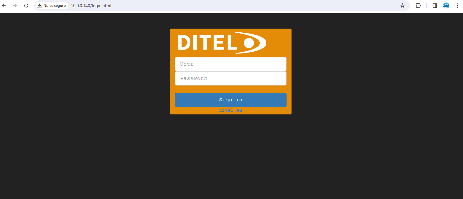
Before you can begin configuring your Micra-M Max device via webserver, you must log in to the software using your account credentials. This ensures secure access to your device settings and configurations.
Accessing the Login Screen: Upon launching the Micra-M Max webserver, you'll be directed to the login screen.
Entering Your Credentials: Enter your log and password in the designated fields. admin/admin are the default credentials. These credentials can be modified when you log in the webserver.
Sign In: After entering your credentials, click the "Sign in" button to access the software dashboard. If your login details are correct, you'll be taken to the main dashboard where you can start configuring your device.
If you encounter any issues during the login process, or if you have forgotten your password, please contact support at ditel.es for assistance.
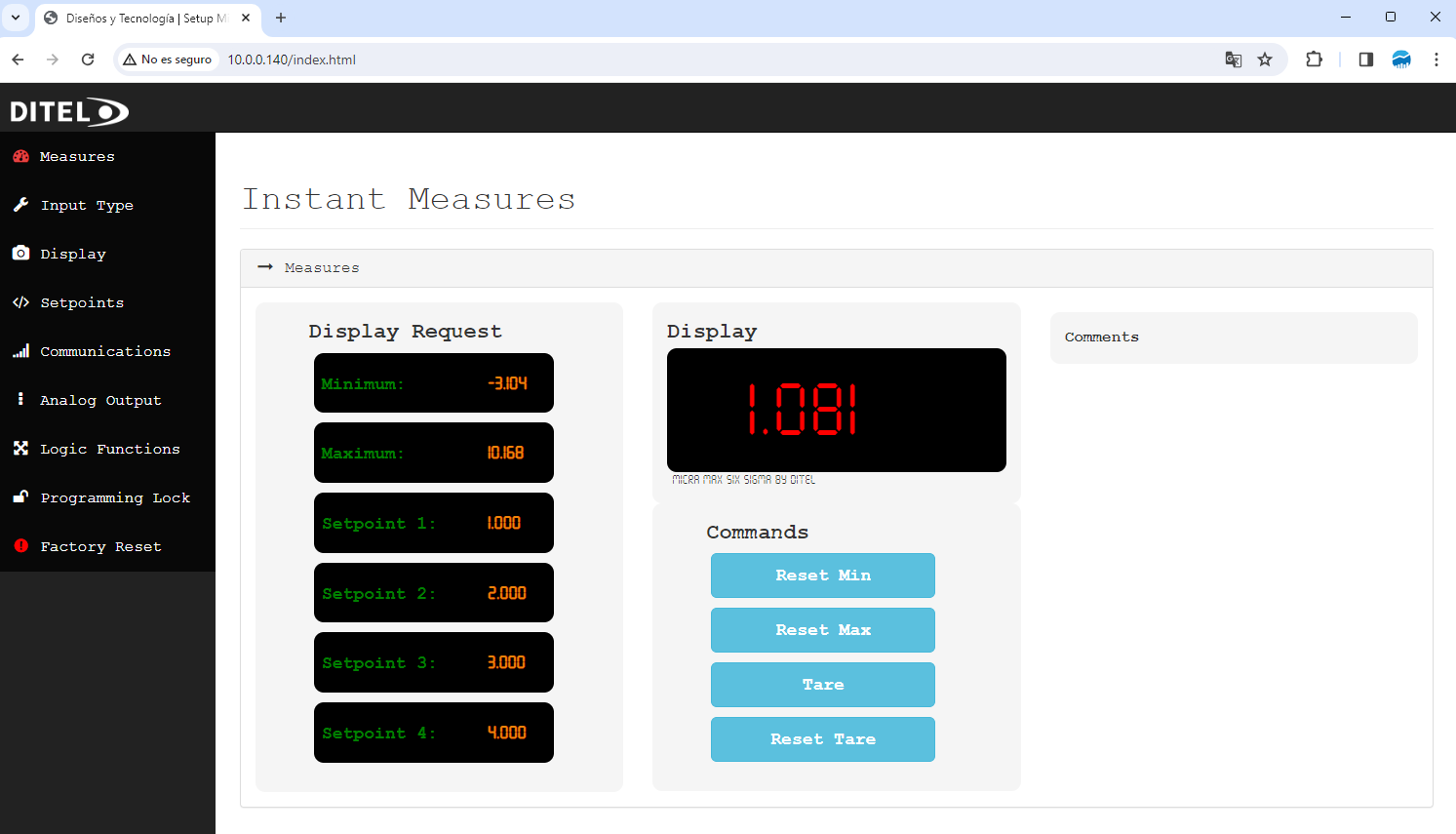
The "Instant Measures" feature of the Micra-M Max software provides real-time data on various measurement parameters. This section of the manual explains how to view and reset these measurements.
Upon navigating to the "Measures" section from the main dashboard, you'll be presented with a comprehensive overview of the current measurement parameters:
Minimum: Displays the minimum value recorded for the selected measurement period.
Maximum: Shows the maximum value recorded for the same period.
Setpoint 1 - 4: Indicates the current values set for each of the four setpoints.
These measurements are dynamically updated, providing instant feedback on the system's performance.
The central display area shows the primary measurement in a large, easy-to-read format. This is the current value measured by the system.
Adjacent to the display, a series of commands allow for direct interaction with the measurement system:
Reset Min: Resets the minimum value to begin recording from the current measurement onwards.
Reset Max: Resets the maximum value to begin recording from the current measurement onwards.
Tare: Adjusts the measurement base to zero, allowing for differential measurements.
Reset Tare: Returns the measurement base to its original state, removing any tare adjustments.
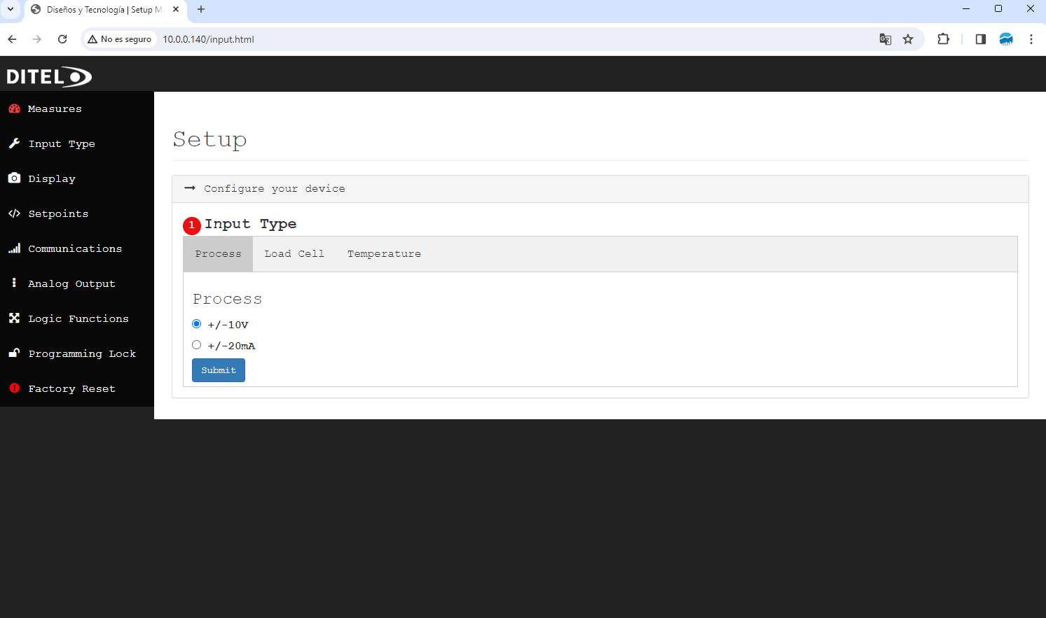
The Micra-M Max software supports various input types to accommodate diverse measurement needs. This section guides you through selecting and configuring the input type according to your specific requirements.
To configure the input type:
Navigate to the "Input Type" section from the main dashboard.
You will see three main input categories: Process, Load Cell, and Temperature. Each category is designed to match specific measurement types and scenarios.
Select "Process" if you are measuring standard process signals. In this mode, you can choose between:
+/-10V: For voltage signals ranging from -10V to +10V.
+/-20mA: For current signals ranging from -20mA to +20mA.
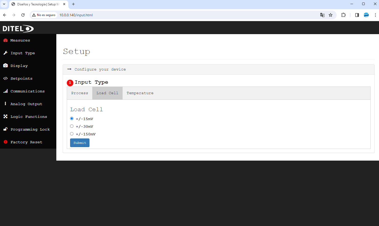
For measuring weight or force via load cells, select "Load Cell" and configure as follows:
+/-15mV: Suitable for low voltage load cell signals.
+/-30mV: For slightly higher voltage requirements.
+/-150mV: For load cells with higher voltage output.
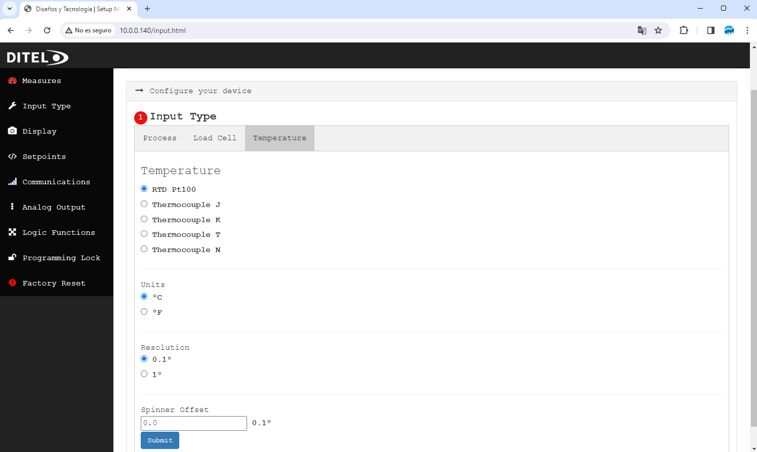
To measure temperature, choose "Temperature" and specify the sensor type:
RTD Pt100: For resistance temperature detectors with Pt100 sensors.
Thermocouple J, K, T, or N: Depending on the thermocouple type you're using.
Additionally, you can set:
Units: Choose between Celsius (ºC) and Fahrenheit (ºF).
Resolution: Select the measurement resolution (0.1º for finer measurements or 1º for broader readings).
Spinner Offset: Adjust the baseline offset for calibration purposes.
After selecting your desired settings within any of the input type tabs, click the "Submit" button to apply your configuration. This action will tailor the Micra-M Max software to accurately interpret signals from your specific input type.
The Display Settings in the Micra-M Max software allow for detailed customization of how data is shown on your device, enhancing user interaction based on the specific needs of your application. This section covers how to adjust these settings for the best user experience.
To modify the display settings:
From the main dashboard, navigate to the "Display" section.
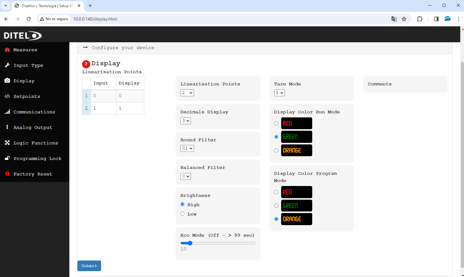
You will encounter a variety of options that can be customized, including Linearisation Points, Decimals Display, and more.
The software supports the adjustment of linearisation points to fine-tune the relationship between the input signal and displayed value:
Adding Points: You can specify up to 11 linearisation points. Each point allows for the input value to be mapped to a specific display value, enabling precise calibration for nonlinear sensors.
Configuring Points: Enter the desired Input and Display values for each point directly in the provided table.
Decimals Display: Choose how many decimal places are shown for measurement values, enhancing precision or simplifying the readout as needed.
Round Filter: Select a rounding filter to apply to the display values, smoothing out minor fluctuations for easier reading.
Balanced Filter: Adjust the balance between responsiveness and stability in the displayed readings with options ranging from 0 (most responsive) to 9 (most stable).
Brightness: Set the display brightness to High or Low, accommodating different lighting conditions.
Eco Mode: Activate Eco Mode to reduce power consumption by dimming the display after a specified time of inactivity (0 to 99 seconds).
Customize the display color to distinguish between different operational modes:
Display Color Run Mode: Choose between Red, Green, and Orange for the normal operating mode.
Display Color Program Mode: Similarly, select a color that will be used when the device is in programming mode, aiding in clear mode differentiation.
Tare Mode: Configure how the tare function behaves, with options to reset to zero under different conditions.
Once you've made your selections:
Review all settings to ensure they meet your requirements.
Click the "Submit" button to apply your changes, which will immediately take effect.
The Micra-M Max software allows the configuration of up to four setpoints, providing flexibility in how the device reacts under specific conditions. This section explains how to set up and customize each setpoint.
To begin setting up your setpoints:
Navigate to the "Setpoints" section from the main dashboard.
You will see options to configure each of the four setpoints individually.
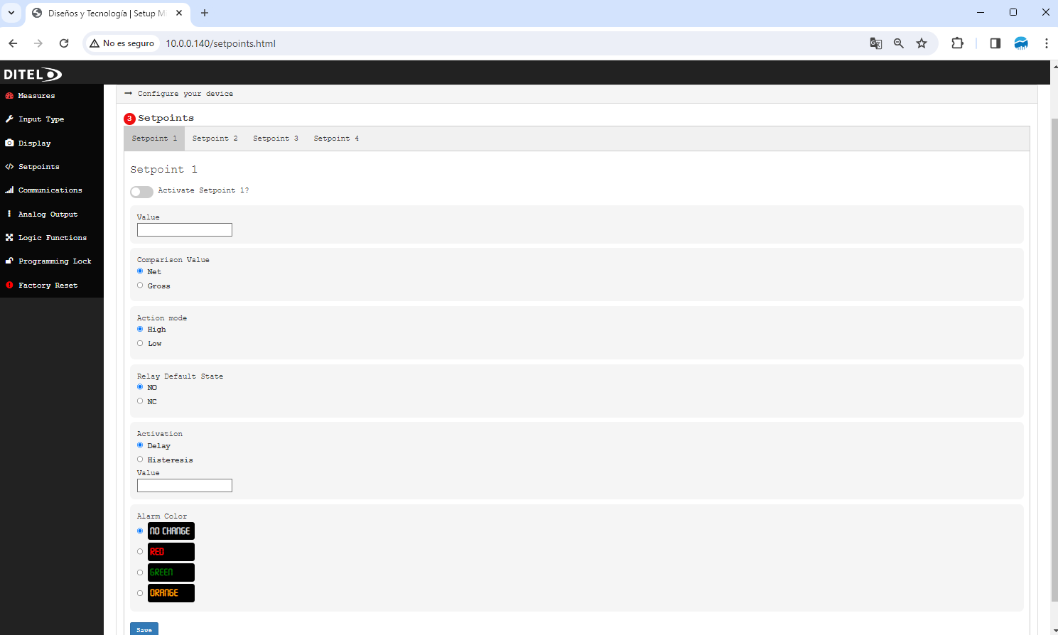
Each setpoint tab allows you to configure the following parameters:
Activation: Toggle to enable or disable each setpoint individually.
Value: Set the trigger value for the setpoint. This is the measurement threshold that activates the setpoint's action.
Comparison Value: Choose between "Net" and "Gross" values for comparison against the setpoint value.
Action Mode: Select "High" if the setpoint action should occur when the measurement is above the set value, or "Low" for below.
Relay Default State: Determine the default state of the relay as "Normally Open" (NO) or "Normally Closed" (NC).
Activation: Specify the activation condition as either "Delay" for a timed response or "Hysteresis" to prevent oscillation around the setpoint value.
Value: Define the delay time or hysteresis margin, respectively.
Alarm Color: Choose the color displayed when the setpoint is active. Options include "No Change", "Red", "Green", or "Orange" to indicate different states or alarms.
After setting the parameters for each setpoint:
Review your configurations to ensure they match your operational requirements.
Click the "Submit" button at the bottom of the form to apply your settings.
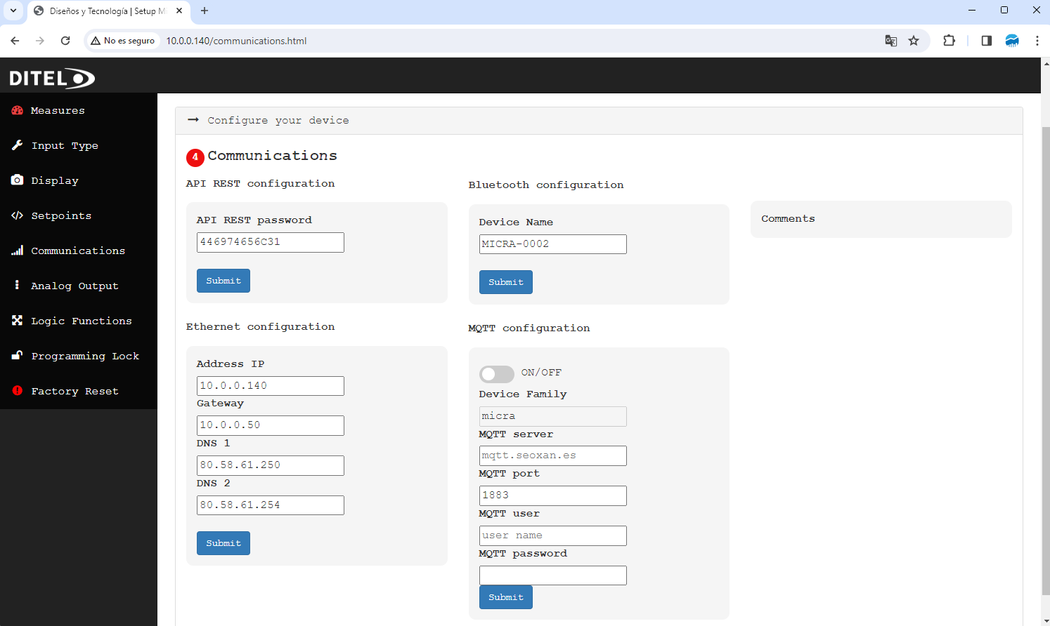
The communications menu provides the interface for configuring the communications of a specific device, offering options for configuring Ethernet, Bluetooth, and MQTT. Below, how to document each section for a user manual is detailed:
This section allows the user to configure the IP address, the gateway, and the DNS servers for the device's Ethernet connection.
IP Address: Field to enter the device's IP address on the network. It must be a valid address in the format xxx.xxx.xxx.xxx.
Gateway: Field to enter the default gateway for the device's network. It must be a valid address in the format xxx.xxx.xxx.xxx.
DNS 1 and DNS 2: Fields to enter the addresses of the primary and secondary DNS servers. It must be a valid address in the format xxx.xxx.xxx.xxx.
Before saving the configuration, ensure that all addresses are valid and within the allowed range for your network.
Allows the user to configure the bluetooth device name. Other configurations must be set on phisical Micra keys.
Device Name: Field to set the name that will be displayed for the Bluetooth device.
Enabling Bluetooth allows wireless connection with other devices.
Facilitates configuring the device's MQTT connection for communication with an MQTT server.
ON/OFF: Switch to enable or disable the MQTT configuration.
Device Family: Pre-configured text field with the value "MICRA", not editable.
MQTT Server: Field to enter the MQTT server address (e.g., mqtt.seoxan.es).
MQTT Port: Numeric field to configure the MQTT server port, with a default value of 1883.
MQTT User and Password: Fields to enter the credentials required for authentication on the MQTT server.
MQTT configuration is essential for integrating the device into automation systems or IoT platforms that use the MQTT protocol for communication.
The analog output settings in the Micra-M Max software enable the device to output analog signals corresponding to measured values, facilitating integration with external control systems or recording devices. This section guides you through the configuration process.
To configure the analog output settings:
From the main dashboard, navigate to the "Analog Output" section.
The configuration panel presents several options to customize the analog output according to your requirements.
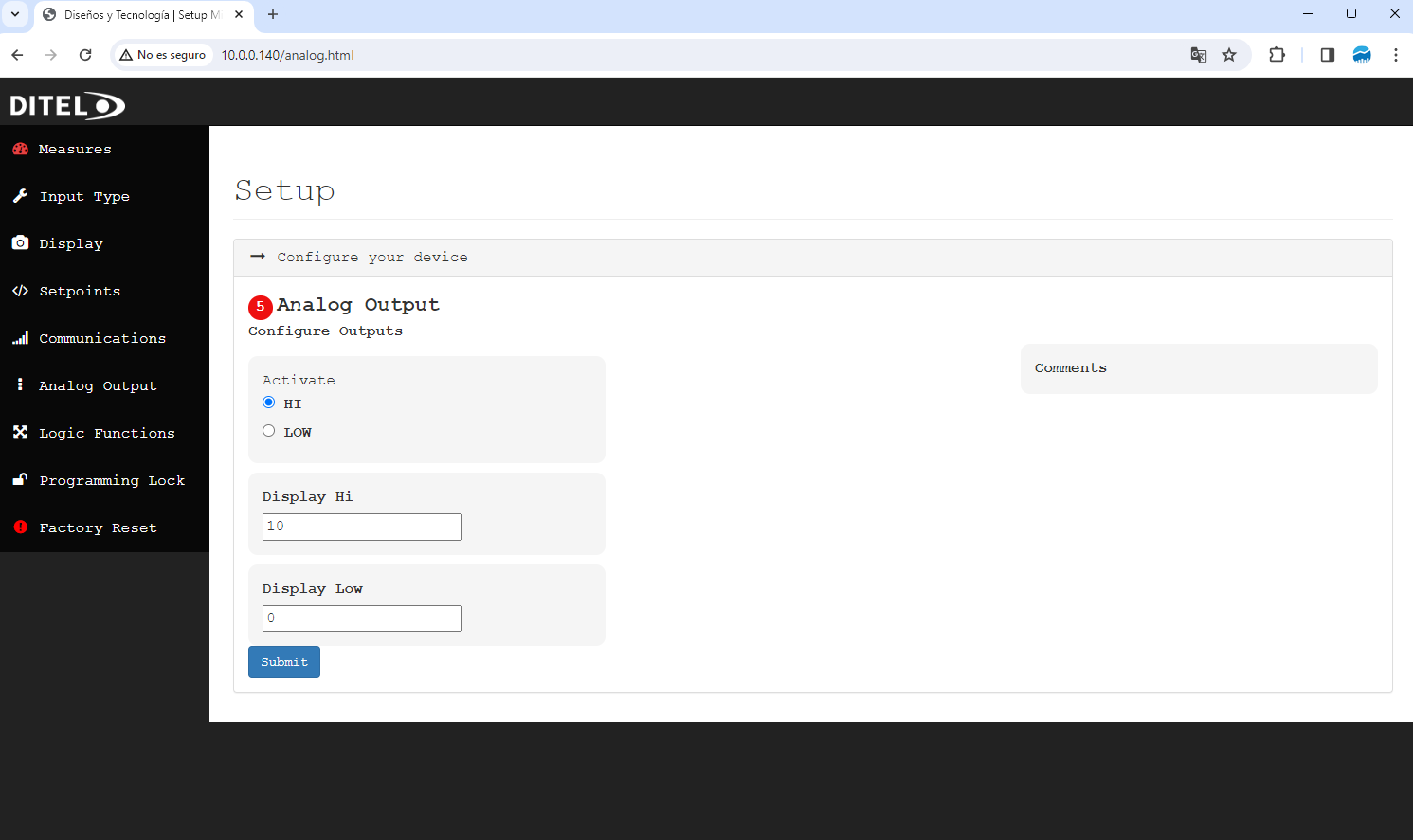
The key settings available for analog output configuration include:
Activation: Toggle the analog output between active (HI) or inactive (LOW) states, controlling whether the output signal is enabled.
Display Hi: Set the upper limit for the analog output range. This value corresponds to the maximum signal output, typically represented in engineering units related to your measurement (e.g., psi, °C, etc.).
Display Low: Define the lower limit for the analog output range, which corresponds to the minimum signal output.
After adjusting the settings to match your operational parameters:
Review all entered values to ensure they align with your system's requirements.
Click the "Submit" button to apply and save your analog output configurations.
The Micra-M Max software provides the ability to configure logic functions, enhancing the device's interactivity and responsiveness to user inputs. This section guides you through configuring these functions for Pins 2, 3, and 4.
To access and configure the logic functions:
Navigate to the "Logic Function" section from the main dashboard.
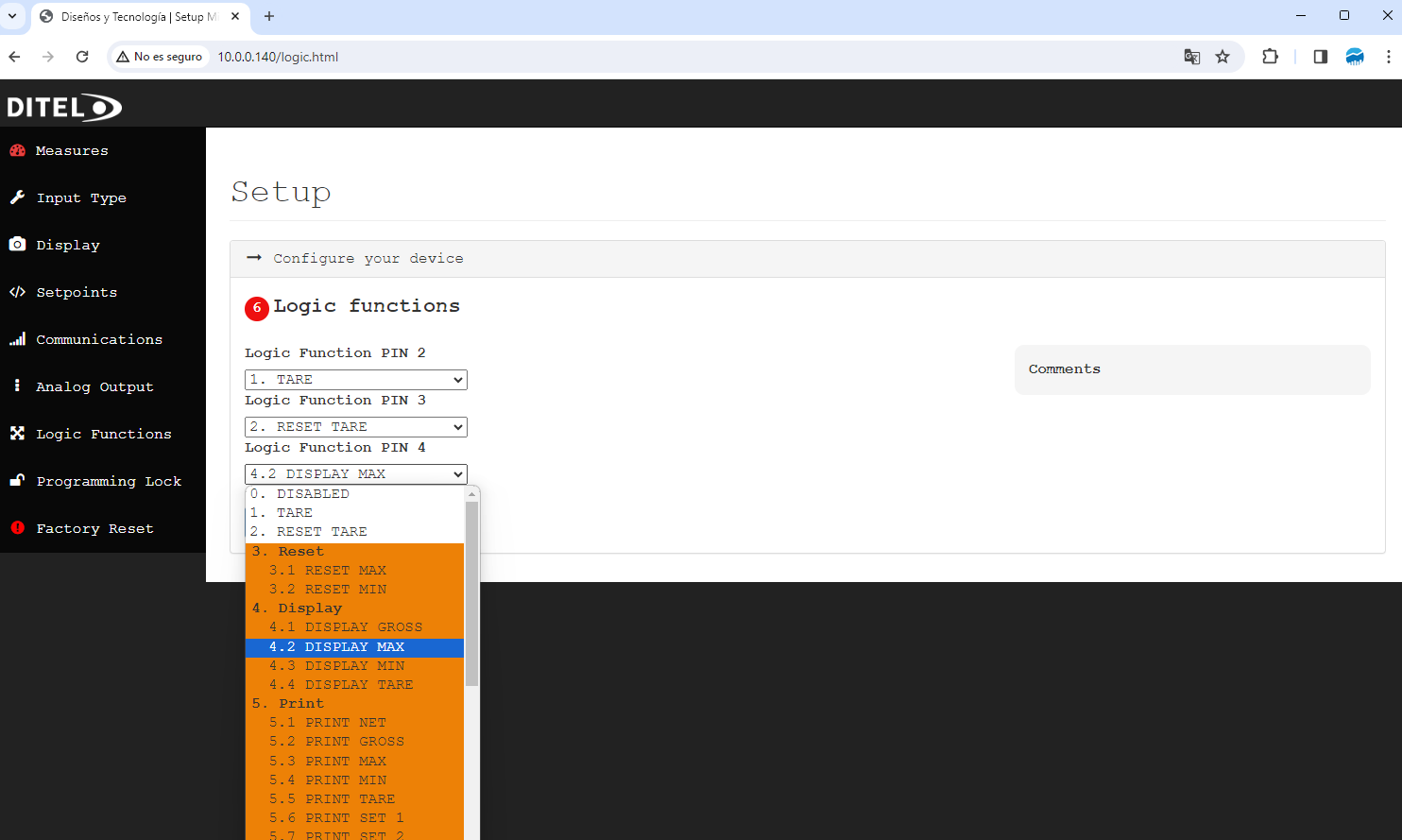
You'll be presented with options to configure the logic functions for Pins 2, 3, and 4.
Each pin can be configured with a specific logic function from the following categories:
Disabled: Turn off any function for the pin.
Tare and Reset Tare: Manage tare settings directly through pin inputs.
Reset: Options to reset maximum, minimum, or other specific parameters.
Display: Change what is currently being displayed (e.g., gross, net, maximum, minimum, tare).
Print: Trigger printouts of measurements or setpoint statuses.
Hold Display: Freeze the current display.
Brightness: Adjust the display brightness between high and low settings.
Change Display Color: Modify the display color to orange, red, or green for visual cues.
Write: Set specific values to tare or setpoints directly through pin inputs.
False Setpoints: Implement temporary setpoint values for testing or other purposes.
Keys Repetition: Allow repeated actions through continuous input.
Reserved: Functions set aside for future use or specific customization.
After selecting the desired functions for each pin:
Review your configurations to ensure they meet your operational needs.
Click the "Submit" button to apply and activate the logic functions.
To safeguard your device's programming configurations, the Micra-M Max software includes a program lock feature. This function restricts access to critical programming settings, ensuring only authorized users can make changes.
From the main dashboard, navigate to the "Programing Lock" section.
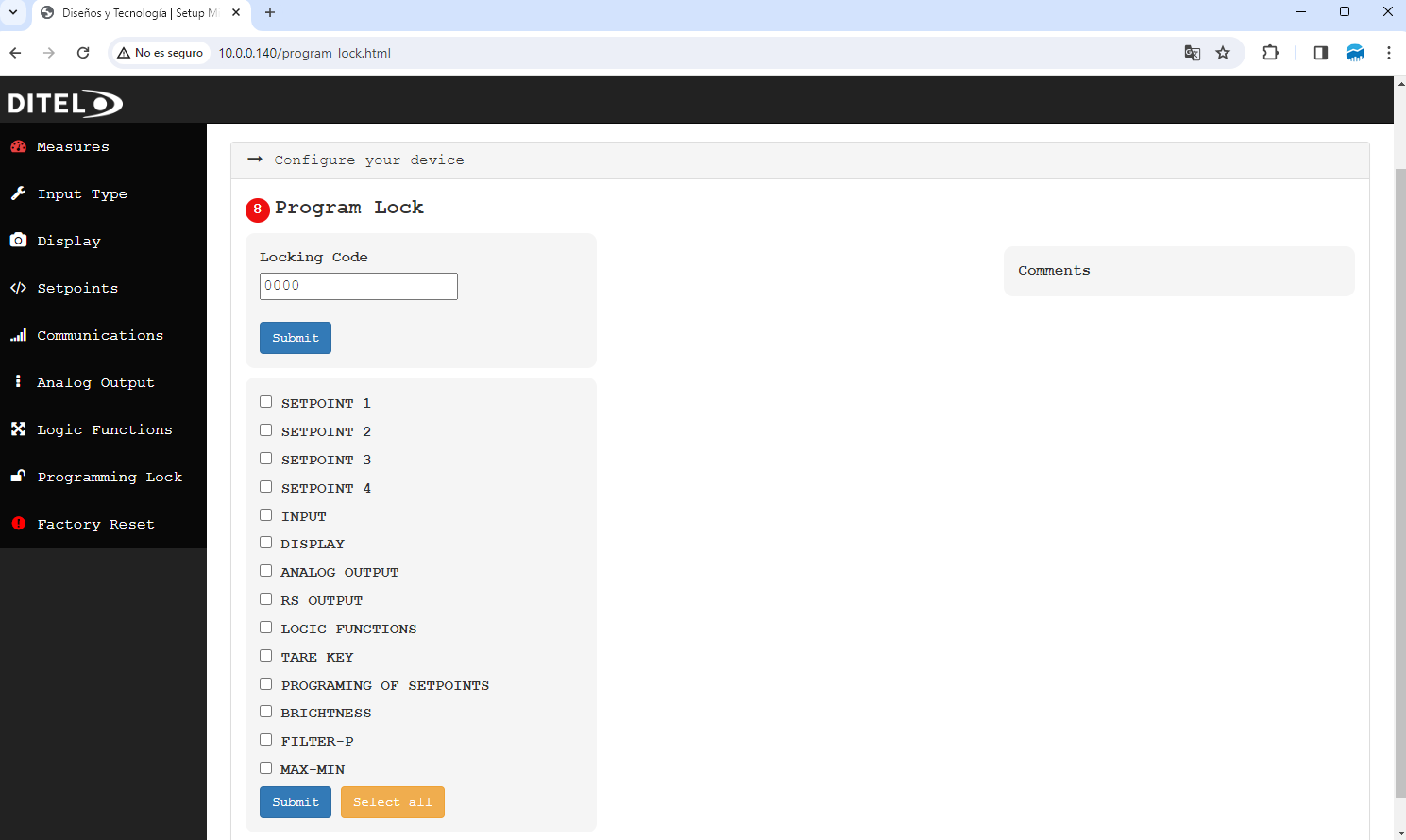
You will be prompted to enter the current lock code to access the configuration settings. This code is either the default set by the manufacturer or one that you have previously established.
After entering the correct code:
1. Choose which settings you wish to lock. Options include:
2. You can select individual items or use the "Select all" option to lock all programmable settings.
3. After making your selections, click "Submit" to apply the locks.
To Change Lock Settings: You must enter the correct lock code to adjust which programming features are locked or unlocked.
To Modify the Lock Code: Refer to the "Locking Code" section of this manual for instructions on changing the program lock code.
A factory reset restores the Micra-M Max software to its original settings, erasing all custom configurations. This procedure should be used cautiously, as it will remove all current settings and data.
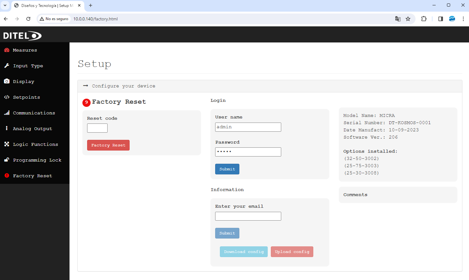
Navigate to the "Factory Reset" section from the main dashboard.
You will be prompted to enter a code to proceed with the factory reset. This code ensures that the reset is conducted by an authorized user. Enter the provided code in the "Enter the code" field.
After entering the correct code, select the "Factory Reset" button to initiate the reset process.
A confirmation dialog may appear to prevent accidental resets. Confirm your intention to proceed with the factory reset.
In addition to factory reset instructions, this section includes steps to change the webserver password:
Go to the "Change password" subsection within the factory reset page.
Enter your new desired password in the "Enter new password" field.
Submit the change by clicking the "Submit" button.